Measurement sites for radiated measurements and object characterization
Besides the standard labor measurement test spaces with mobile measurement equipment, we have two own "fix" measurement sites with dedicated RF-specifications. One of each is:Open test range
Open test range. The device under test is mounted on a dielectric platform that can be elevated by the semi automated steering system.
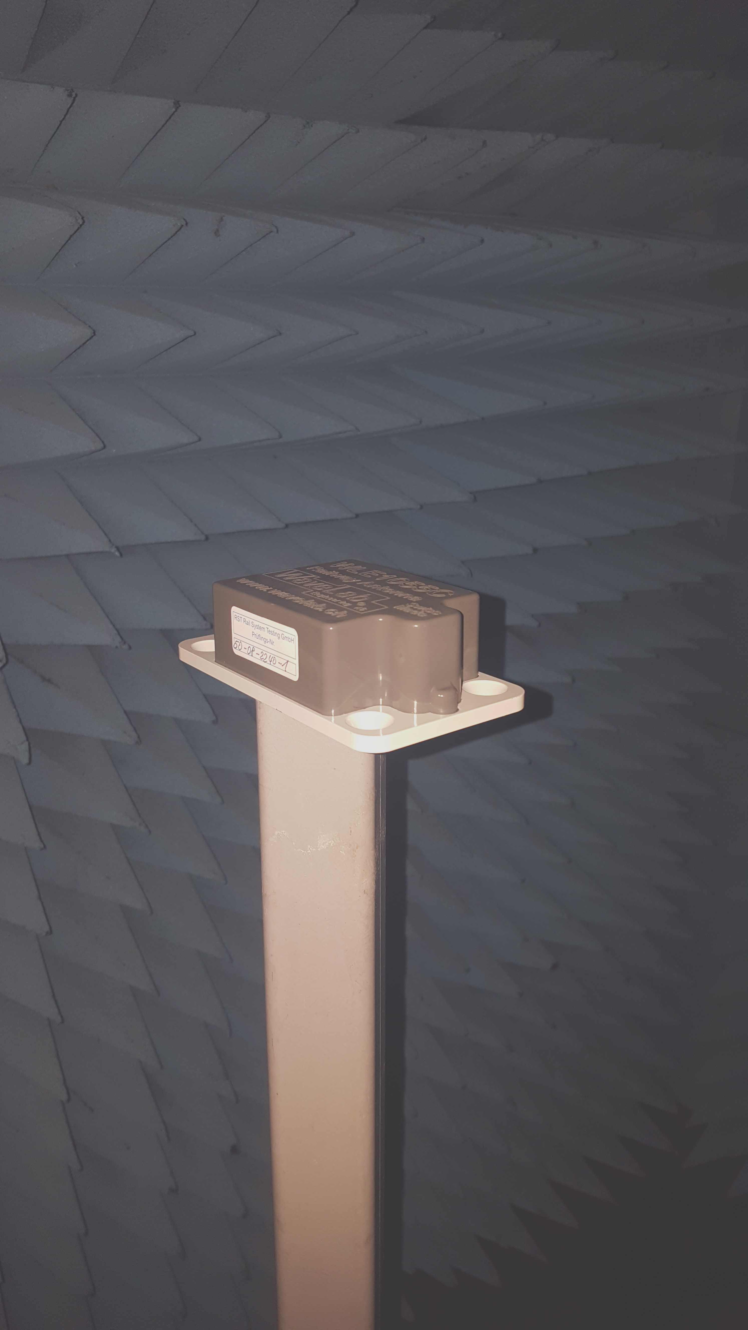
Open test range. The receiving antenna is mounted on the dielectric mast. The antenna can be rotated along the polarization axis by steps of 5°.
The open test range has following core specifications:
- Distance between the two dielectric masts: 15m
- Maximal achievable height over terrain with both masts: 6m
- Controlling of measurement height: Made by a laser measurement system attached to the DUT-platform
- Typical reference antenna1: WLE1058A, LogPer-Antenna 100 MHz to 2.5 GHz (3 GHz typical)
- Typical reference antenna2: QRH18, Quadridged-Antenna 1 GHz to 18 GHz
- Measurement control system: LabView
- Measurement instruments: Selective receiver or vector network analyzer, dependent of the measurement task
- The extensions of the measurement platform are finished
3D-Antenna pattern measured in one shot
The axis extension of the positioner allows to measure the DUT in one shot over the whole surface of the sphere. It does not matter if the DUT itself emits the signal or if the measurement signal is generated with the VNA and applied to the DUT.
Measured, normalized Antenna Gain. The DUT is sweept over the requested angular Theta and Phi ranges while the co- and cross polar signal portions are recorded. Out of them are the single polarization elements calculated for display in the graphs.
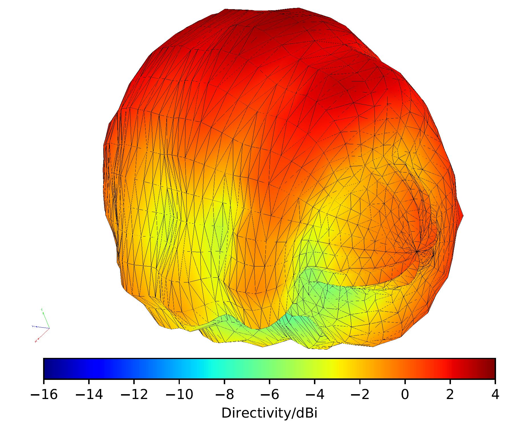
3D Antenna Pattern. The recording of the data is made in one setup. The co- and the cross polar portions are recorded, out of them are the single polarizations calculated and displayed.
Shielded anechoic chamber
The anechoic chamber upgrade is finished. The covered frequency range starts at 500 MHz and ranges up to 40 GHz. The upper frequency limit is mainly driven by the test instruments and is not limited by the absorbing elements.
Anechoic Measurement Chamber. The surfaces and structure elements below the absorbers are with an excellent conductive surface coated, preventing external signals entering into the chamber.
Anechoic measurement chamber . All surfaces are completely covered by absorbing elements, making sure that incident waves are absorbed by 30dB and more. This leads to the fact that the reflected energy has a very, very low level.
Advantages of the two measurement sites
Through the availability of the two measurement sites are we very flexible to measure your emitting unit under tests or to characterize your antennas. Dependent of the measurement job are we using VNA's or selective receivers to operate the site. This allows high flexibility to make customized measurement setups. The devices under test and the used measurement equipment are controlled by LabView, allowing higher efficiency and excellent reproducibility. By doing so, the measurement processes are standardized and automated.- Home
- Research & Development
- Projects/Coaching
- Measurement Sites
- Simulation Tools MWO & VSS
- Antennas and IoT
- References
- Jobs
WaveLab Engineering AG ! !
Just come and see us for the fast and precise execution of your radiated measurement jobs.
Just come and see us for the fast and precise execution of your radiated measurement jobs.
© 2021 WaveLab Engineering AG
WaveLab Engineering AG, Gewerbestrasse 11
CH-3053 Lätti b. Münchenbuchsee
Tel. +41 31 868 44 66 Fax. +41 31 868 44 60
WaveLab Engineering AG, Gewerbestrasse 11
CH-3053 Lätti b. Münchenbuchsee
Tel. +41 31 868 44 66 Fax. +41 31 868 44 60