
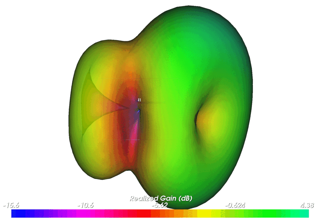
Electromagnetic fields are invisible, yet they are the foundation of cellular communications, Wi-Fi, and wireless sensor systems. High-frequency alternating current generates time-varying electric and magnetic fields at the antenna. The major part of the energy is radiated as electromagnetic waves that propagate through three-dimensional space. The antenna’s radiation pattern describes how this energy is distributed across different directions.
The Surrounding Environment Makes a Difference
Inside a finished product, an antenna never operates in isolation. Printed circuit boards, batteries, metal components, and enclosure materials all influence its electromagnetic environment. Human or animal tissue can also affect radiation performance, particularly in devices worn close to the body.
As a result, the same antenna can exhibit significantly different radiation characteristics when integrated into a product and used under real-world conditions compared to operating in free space.
Antenna Integration and Wireless Coexistence
Antennas are expected to fit seamlessly into increasingly compact devices without compromising their design. Limited space and predefined mounting positions often require trade-offs. Many products also incorporate multiple antennas, where unwanted coupling can affect overall performance.
Wireless coexistence presents another challenge. A strong transmitted signal can couple into the receive path of another wireless system, potentially driving its receiver low noise amplifier into compression – even when the systems operate in different frequency bands.
Careful antenna placement, sufficient isolation, and appropriate filtering help minimize these effects and support reliable operation.
Making Real-World Radiation Patterns Visible
Simulations and antenna specifications provide valuable starting points. But how does the fully assembled product actually radiate?
Three-dimensional antenna radiation pattern measurements provide the answer.
By measuring the product across a spherical surface, covering directions throughout three-dimensional space, its radiation characteristics can be captured and visualized as a 3D pattern.
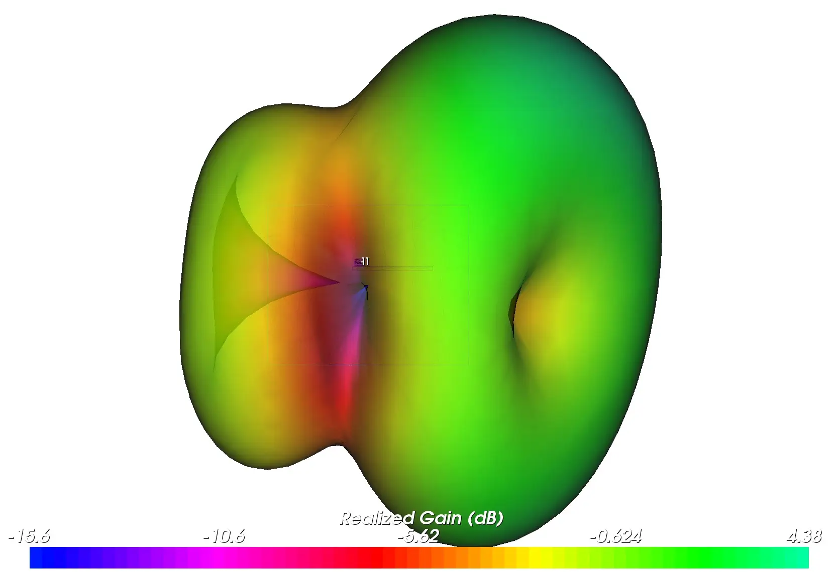
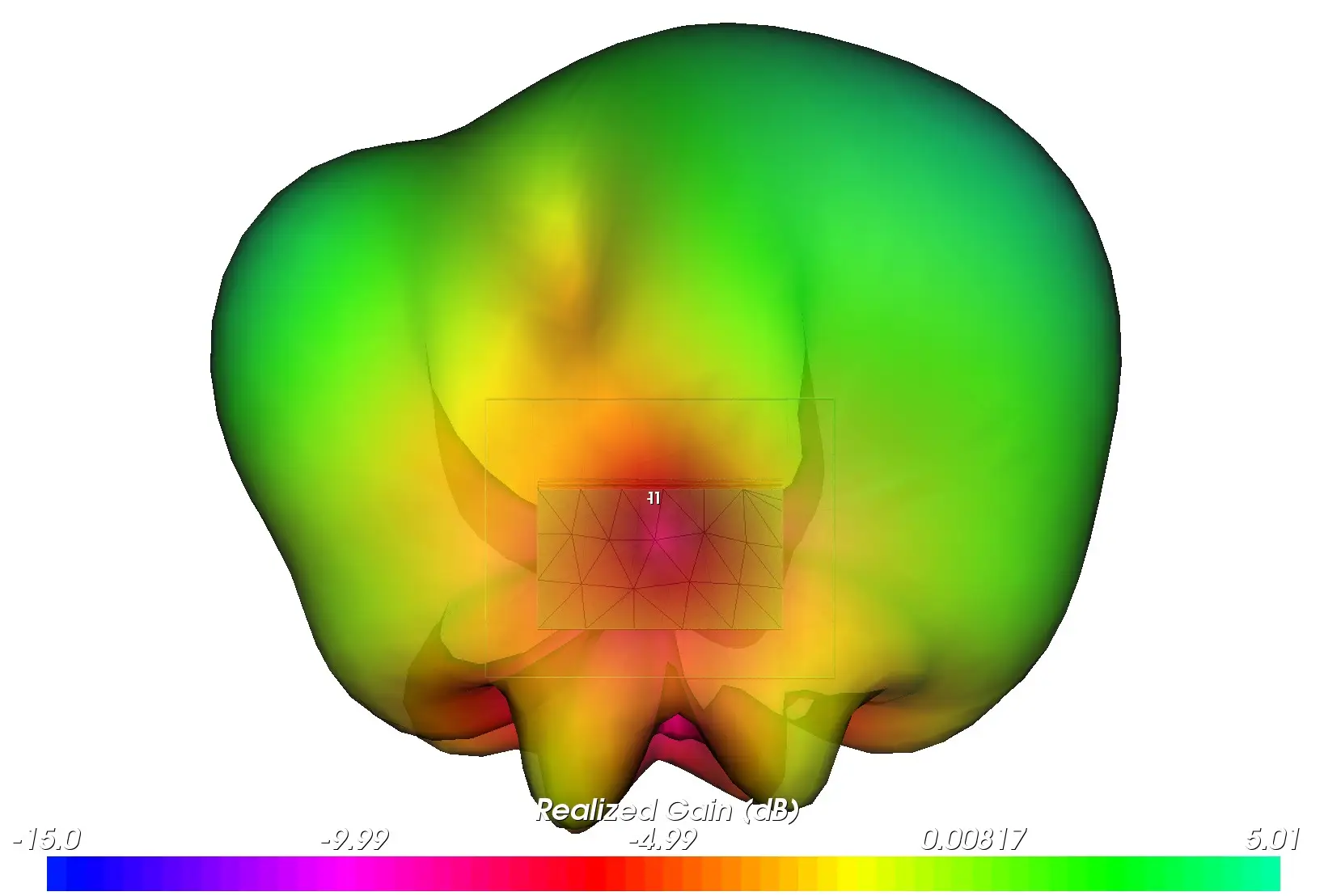
Radiation lobes reveal the directions of strongest radiation, while indentations and nulls highlight areas of weak radiation.
Comparing different configurations provides particularly valuable insights: How does the enclosure affect radiation? What changes when the antenna is repositioned? How does operating close to the body influence performance? And do multiple antennas provide complementary coverage, or do they leave unexpected coverage gaps?
However, the 3D visualization alone does not tell the whole story. Quantitative measurements such as realized an-tenna gain, total radiated power (TRP), and the radiation efficiency are essential for evaluating how effectively a product radiates its transmitted energy.
What You Can’t See, We Make it Visible
A well-matched antenna does not automatically guarantee a reliable wireless connection. What truly matters is how the antenna interacts with the electronics, enclosure, and intended operating environment.
3D radiation pattern measurements reveal where the finished product actually radiates its energy – and where potential weaknesses may exist.
These insights help engineers understand design trade-offs, identify opportunities for improvement, and objectively compare different product configurations.
Do you have any questions or would like to learn more about optimizing your radio-frequency designs, our experts at WaveLab Engineering are happy to help.
